Geometric Dimensioning and Tolerancing Powers Flawless Automobile Manufacturing Through 5 Critical CNC Precision Standards
The automobiles that are manufactured today are one of the most complicated machines that have ever been produced in large quantities, consisting of thousands of parts that are exactly manufactured and they all fit with each other to ensure safe and reliable transportation. The reason is that behind any vehicle coming out of the assembly line is an elaborate system of specifications and measurements that make parts fit each other perfectly and work as expected. The core of this precision manufacturing system is the geometry dimensioning and tolerancing which is often referred to as GD&T, a universal language that specifies exactly how automotive parts should be produced using CNC machining technology.
Gaining knowledge of geometric dimensioning and tolerancing provides an opportunity to have a glimpse of the process by which automotive engineers and manufacturers are able to produce remarkable consistency and reliability that modern vehicles require. To any automotive engineer, manufacturing career, or just any interested individual who is wondering how a car is made, understanding these basic concepts will prove useful information about one of the most needed fields in the manufacturing industry.
What Geometric Dimensioning and Tolerancing Actually Means
Geometric dimensioning and tolerancing is a standardized engineering tolerances definition and communication system. As opposed to just saying that it should be a 10 millimeters hole, GD&T gives a picture of the entire picture on how that hole should be placed, oriented and shaped in comparisons with other parts on the part.
The system provides acceptable variances of a component geometry at the level of symbols, numbers, and reference frames. Not a single manufactured part is in the exact shape desired as it is impossible to manufacture a perfect part. GD&T establishes the amount of variation that is admissible and still maintain the part as operational.
The conventional dimensioning techniques merely give size tolerances, e.g. a shaft should be 9.95-10.05 millimeters in diameter. But this has nothing to say as to whether or not the shaft is straight or centered or perpendicular to the mounting surfaces. Geometric dimensioning and tolerancing bridges these gaps by managing such aspects as straightness, flatness, perpendicularity, concentricity, and position.
The ASME Y14.5 standard defining GD&T practices in the entire manufacturing of North America has been developed and is maintained by the American Society of Mechanical Engineers. Such standardization implies that engineers working in various companies, states, or countries can clarify the precise requirements without any confusion.
Why Automobiles Demand Precise Geometric Dimensioning and Tolerancing
The manufacturing of automotive goods is associated with its own set of challenges that necessitate the use of geometric dimensioning and tolerancing in its entirety. Cars work in very harsh conditions such as vibration, changes in temperature, exposure to chemicals, and mechanical work, without compromising on safety and performance.
Take the case of a basic engine device such as a piston. This component is required to slide and roll in the bore of the cylinder thousands of times per minute and still keeping the oil film clearances satisfactory, but not allowing escaping of combustion gases. Unless the piston is perfectly round or the cylinder bore straight, the engine will waste oil, lose power or simply come to a disastrous end.
Safety critical systems require stricter control. Steering mechanisms, brakes, and structural parts are supposed to be of the most precise standards since the lives of people are dependent on their stable functionality. National Highway Traffic Safety Administration states that thousands of accidents per year are caused by mechanical failures, some of which are caused by manufacturing defects that are avoided by proper geometric dimensioning and tolerating.
The requirements are increased by mass production. Car manufacturers manufacture millions of cars every year, and they need replaceable components which stack up every time. This would not be possible without some standardization of tolerancing practices.
Core GD&T Concepts Applied in Automotive Manufacturing
Several fundamental concepts form the foundation of geometric dimensioning and tolerancing as applied to automotive components manufactured through CNC machining processes.
Datum reference frames establish the coordinate system from which all measurements originate. In automotive applications, datums typically represent mounting surfaces, bolt holes, or other features that define how the part connects to other components. A cylinder head, for example, uses the deck surface and bolt hole pattern as datums because these features determine its relationship to the engine block.
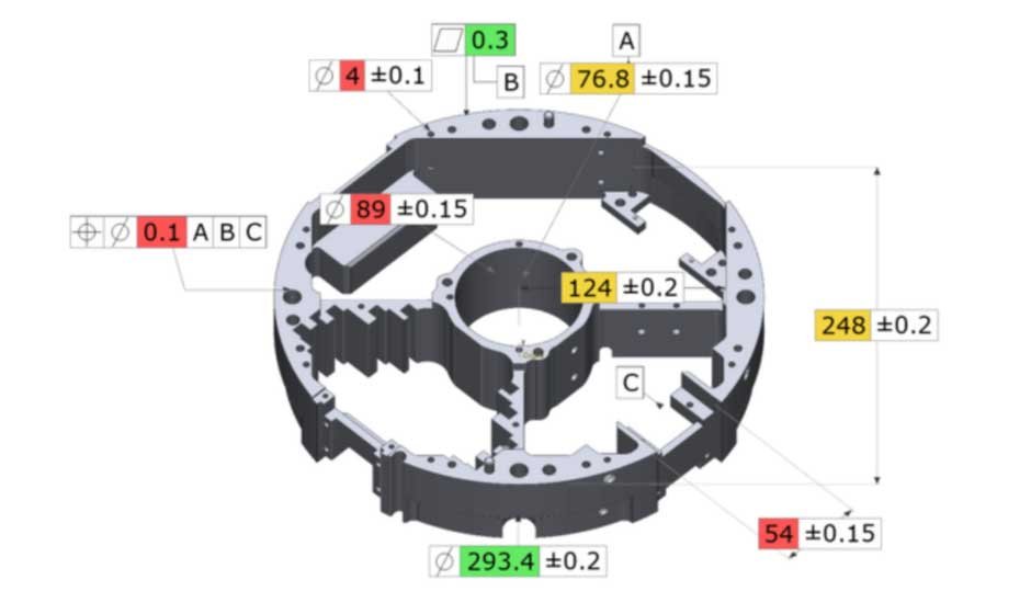
Feature control frames are the rectangular boxes containing GD&T symbols that appear on engineering drawings. These frames specify which geometric characteristic is being controlled, the allowable tolerance, and which datums provide the reference frame. Reading these frames correctly is essential for machinists producing automotive components.
Material condition modifiers account for how tolerances interact with size variations. Maximum Material Condition applies when a feature is at its largest allowable size for external features or smallest for internal features. These modifiers allow designers to optimize tolerances based on real-world assembly conditions.
Geometric characteristics include fourteen specific controls divided into categories. Form controls like flatness and straightness apply to individual features. Orientation controls like perpendicularity and parallelism define relationships between features. Location controls like position and concentricity specify where features must be located. Profile controls define complex three-dimensional shapes.
How CNC Machining Achieves GD&T Requirements in Auto Parts
Computer Numerical Control machining represents the primary manufacturing method for creating automotive components that meet geometric dimensioning and tolerancing specifications. CNC equipment translates engineering drawings with GD&T callouts into precise machine movements that create parts matching design intent.
Modern CNC machines achieve positioning accuracy measured in micrometers, with repeatability that ensures identical parts across production runs. This precision enables automotive manufacturers to meet the tight tolerances geometric dimensioning and tolerancing specifications demand.
The CNC programming process begins with CAD models and drawings containing GD&T specifications. Programmers determine machining sequences, tool selections, and cutting parameters that will achieve required geometric characteristics. For example, to achieve perpendicularity between two surfaces, the programmer might specify facing operations using the datum surface as a reference, ensuring proper orientation.
Workholding fixtures play a critical role in achieving GD&T requirements. These fixtures must accurately establish the datum reference frame, clamping the workpiece in precise alignment with machine axes. Poor fixturing can make achieving geometric tolerances impossible regardless of machine capability.
Tool selection impacts which geometric characteristics can be achieved. Specialized tools like boring bars with adjustable cutting tips enable precise diameter and position control. Form tools create specific profiles. Threading tools produce accurate thread geometry meeting position and orientation requirements relative to datum features.
Critical Automotive Components Requiring Strict GD&T Control
Many automotive systems are dependant on components that are produced to the very specifications of geometric dimensioning and tolerancing by CNC machining. The knowledge of such applications explains why GD&T is important in actual vehicles performance and safety.
Perhaps the most geometrically complicated automotive parts are engine blocks and cylinder heads. The bores of the cylinders should be round, parallel and at right angles to the deck. Bores of camshaft and crankshaft have to be positioned and oriented, to allow correct alignment. There are GD&T requirements in coolant passages, oil galleries and mounting surfaces.
Transmission housings also have a high position tolerance of bearing bores that carry rotating shafts. Gear engagement relies on appropriate shaft alignment, which means concentricity and perpendicularity are of great importance. The control of flatness is needed in mounting surfaces to ensure that they are not distorted by being bolted onto the engine or vehicle structure.
Components of the brake system such as calipers, rotors and mounting brackets contain safety-critical GD&T requirements. Rotor runout, the degree of the rotor wobble during rotating, has to be minimised in order to avoid the brake pulsation and consistent stopping behaviour. Perpendicularity of the surface on which the caliper is mounted ensures that the pads wear evenly.
Suspension parts such as control arms, knuckles and mounting brackets are dependent on GD&T to retain the geometry of the wheel alignment. Bores of ball joints and bushing must be able to meet position tolerances to obtain correct camber, caster and toe angles. Directional deviations result in untimely wear and control issues in the tires.
The components of the fuel system such as injector bodies, fuel rails, pump housings need accurate positions and orientations of the holes to ensure good sealing and flow characteristics. Geometric errors may lead to leaks, ineffective combustion or pressure loss that may affect engine performance.
Reading and Interpreting GD&T Symbols on Automotive Drawings
Engineers, quality inspectors, and machinists must understand GD&T symbology to manufacture and verify automotive components correctly. While the complete symbol set includes dozens of elements, several appear most frequently in automotive applications.
The position symbol shown as a circle with crosshairs controls the location of features like holes or studs. This is probably the most commonly used GD&T control in automotive manufacturing because so many components connect through bolted joints requiring accurate hole patterns.
The perpendicularity symbol represented by a rectangle and line at a right angle ensures features maintain 90-degree relationships to datum references. This frequently appears on mounting surfaces that must mate squarely with other components.
The concentricity symbol shown as two concentric circles controls how closely cylindrical features share a common axis. This is critical for rotating components like crankshafts where off-center features cause vibration and premature bearing wear.
The profile symbol appears as either a half-circle representing profile of a surface or a circle representing profile of a line. These powerful controls define complex three-dimensional shapes common in automotive body panels and aerodynamic components.
The flatness symbol represented by a parallelogram controls surface variation. This appears on gasket surfaces, mounting pads, and other areas where even contact is essential for sealing or proper load distribution.
Measuring and Verifying GD&T Specifications in Production
The challenge is not just to make parts that satisfy the geometric dimensioning and tolerating requirements. Manufacturers also need to check the compliance by means of the accurate measurement and inspection.
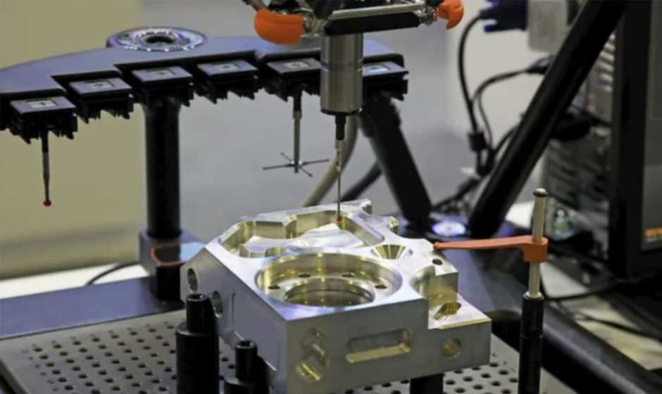
The gold standard of GD&T verification is that of coordinate measuring machines. These are automated machines which have touch probes that measure features of parts in three dimensions as compared to real geometry versus CAD models and GD&T specification. In the current design of CMMs, the highly intricate parts of the automotive are examined within minutes, measuring hundreds of dimensions and geometric features.
The optical comparators cast an image of parts onto a screen with overlay drawings that can be visually checked to verify the profiles and locations of features. They are still used in high volume production inspection due to their quick nature and easy operation.
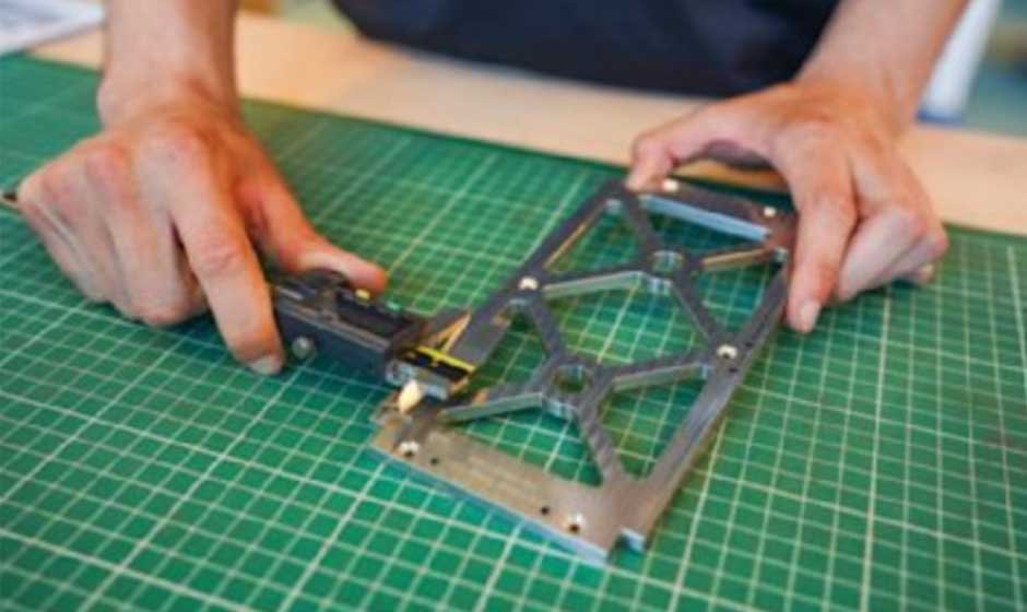
The basic tools used to test parallelism, flatness and perpendicularity are height gauges and surface plates. These mechanical measurement tools are traceable to national standards and they do not need advanced programming or installation.
Functional gauging involves special fixtures, which physically check part compliance to GD&T requirements. Go/no-go checks are used to determine holes are in tolerance of position and check assembly relationships of fixtures. These instruments allow quick check-up of the production line by non-metrology operators.
The statistical process control helps to monitor trends in production so that they can identify the issues before the part is out of toleration. Manufacturers are able to monitor measurements with time so as to adjust CNC programs or tool offsets to achieve the optimum geometric properties during production runs.
Real-World Impact of GD&T on Vehicle Quality and Performance
The graphic characters and figures in geometric dimensioning and tolerancing specifications correspond directly into practical advantages to the vehicle users and car makers.
One of the largest automakers in the US narrowed the scope of complaints about engine oil consumption to the geometry of the cylinder bores. The inquiry disclosed that bore diameters were within the traditionally acceptable tolerance of size; however, the variation in straightness and roundness were greater than what was acceptable in GD&T requirements. Engines were burning too much oil as even the piston rings could not keep the correct sealing around the out-of-round bores. The problem was solved by using tightening of the geometric tolerancing and enhancement of machining processes.
One of the luxury car manufacturers was having a problem with wind noise at highways. It was analysed that there were excessive gaps between body panels in spite of the parts complying with the minimum dimensions requirements. The use of profile tolerancing in exterior panel and tightening position control on mounting holes minimized the gaps and noise complaints and customer satisfaction improved dramatically.
One company making electric cars found the use of different shapes in battery pack housings led to thermal issues. The size tolerances of individual components were met, but there were accumulated geometric errors that made it impossible to seat cooling plates properly. The solution to the thermal problems and better battery life was the implementation of extensive GD&T during the assembly of the house and enhancement of the CNC fixturing techniques.
Challenges in Implementing GD&T in Automotive Manufacturing
Although it has advantages, there are major challenges that geometric dimensioning and tolerancing in automotive production have that must be tackled by the manufacturers.
The training needs are high since GD&T is a complicated technical field. Engineers should be taught to make use of tolerances in the design. Machinists should know the impact of their work on geometric properties. Quality inspectors have to read specifications and measurement results properly. This is an expensive and lengthy training investment.
The complexity of measurement is growing with geometric tolerancing. Simple calipers or micrometers may be needed in traditional dimension inspection, whereas coordinate measuring machines or special gauges may be necessary in GD&T verification. This equipment is a great capital expense and needs highly qualified operators.
The interpretation differences may arise due to the fact that GD&T also has several ways to tolerance a given feature. In the absence of effective communication between the design and manufacturing facilities, the parts could be made to fit correctly as per the drawing and fail to work. These problems can be avoided by regular coordination meetings and documentation.
Geometric tolerancing increases the complexity of the tolerance stack-up analysis. Designers need to be aware of how tolerances add up with assemblies to make sure that components are fitting and operating correctly. This analysis is assisted by tools that are provided by software, which needs training and the input of datum schemes and tolerance relationships.
Future Developments in GD&T and Automotive Manufacturing
Geometric dimensioning and tolerancing continues evolving alongside advances in manufacturing technology and vehicle design. Several trends are shaping how automotive companies apply GD&T specifications.
Model-based definition eliminates traditional 2D drawings, embedding GD&T specifications directly in 3D CAD models. This approach reduces ambiguity and enables automated programming of CNC machines and coordinate measuring machines directly from design data. Many automotive manufacturers are transitioning to fully model-based workflows.
In-process verification using probing systems on CNC machines allows geometric characteristic checking during machining rather than after completion. This enables real-time adjustments to maintain tolerances and reduces scrap from out-of-specification parts.
Artificial intelligence applications are emerging to optimize tolerance specifications. Machine learning algorithms analyze manufacturing data to recommend tolerance values that balance cost, quality, and functional requirements. These systems help designers apply GD&T more effectively.
Additive manufacturing integration requires extending GD&T principles to 3D printed components. As automotive companies increasingly use additive processes for production parts, standards organizations are developing guidance for tolerancing these unique manufacturing methods.
Frequently Asked Questions About Geometric Dimensioning and Tolerancing in Automobiles
What makes geometric dimensioning and tolerancing better than traditional tolerancing methods?
Geometric dimensioning and tolerancing provides complete control over how parts are manufactured and assemble together. Traditional methods only specify size limits, leaving geometric relationships undefined. GD&T eliminates ambiguity by controlling form, orientation, location, and profile explicitly. This ensures parts function correctly and fit together properly regardless of size variations within tolerance ranges.
Do all automotive components require GD&T specifications?
Not every feature on every part needs geometric tolerancing. Designers apply GD&T to critical characteristics affecting function, assembly, or safety. Simple components with non-critical features might use traditional dimensioning. However, most automotive parts have at least some GD&T specifications because modern vehicles demand precise component relationships for proper operation.
How does GD&T affect automotive manufacturing costs?
Initially, implementing GD&T increases costs through training, measurement equipment, and more complex programming. However, it ultimately reduces costs by decreasing scrap, eliminating assembly problems, and improving reliability. Parts manufactured to proper geometric tolerances assemble easily without rework, and vehicles experience fewer warranty claims from component failures.
Can older CNC machines achieve GD&T requirements?
Machine age matters less than capability and condition. Well-maintained older machines with adequate accuracy, rigidity, and proper fixturing can meet many GD&T requirements. However, extremely tight tolerances might exceed older equipment capabilities. Manufacturers must match part requirements to appropriate machines, sometimes reserving critical features for the most capable equipment.
How do engineers determine appropriate GD&T tolerances?
Tolerance selection balances functional requirements against manufacturing capability and cost. Engineers analyze how parts interact, calculating minimum tolerances ensuring proper function. They then consult with manufacturing to verify achievability and adjust specifications as needed. This collaborative approach prevents specifying tolerances tighter than necessary while ensuring adequate control.
What happens when parts don’t meet GD&T specifications?
Out-of-specification parts typically require disposition decisions. Engineers review measurements to determine whether deviations affect function or safety. Minor excursions might be acceptable through deviation approval processes. Parts with critical variations require rework if possible or scrapping if not. This decision-making process balances safety, quality, and economic considerations.
Building a Foundation in Geometric Dimensioning and Tolerancing
Knowledge of geometric dimensioning and tolerancing and how it applies in CNC machining of automotive manufacturing is a valuable study to any engineer or other manufacturing career. This standardized system allows the accuracy and consistency that the modern cars require as well as the universal way of communication between the design and manufacturing team.
With increasing automotive technology of electric powertrains, autonomous systems, and new materials, geometric dimensioning and tolerancing is becoming even more critical. These complex cars need an unprecedented attention to the components manufacturing and assembly, which makes GD&T expertise even more valuable.
But whether you are studying automotive engineering, looking at manufacturing career opportunities, or just interested in the construction of complex machines, the understanding of the significance of geometric tolerancing gives you a chance to see some of the underlying principles that make the manufacture of modern automobiles viable. The further advancement of GD&T standards and measurement technology will be developmental in the way cars are created and manufactured in the next several decades.